Flare units
To ensure smokeless combustion of gases and gas emissions that are regularly or periodically generated during the production process, it is customary to use flares. This equipment is also intended for the preparation and processing of extracted oil and gas in chemical and oil refineries.
Flare units are designed for disposal of well products. Flare units can be vertical, horizontal, or closed.
Types of flare units:
- Flare unit for burning oil and gas condensate;
- Horizontal flare unit for industrial waste disposal;
- Horizontal flare unit for gas combustion;
- Vertical flare installation for gas combustion;
- Mobile units on a frame base or chassis.
Torch ignition system
- The operator opens the supply of fuel gas from the fuel pipeline or, in its absence, from the gas cylinder installation and checks the pressure;
- Then presses the “Start” button on the control cabinet and starts the program;
- After this, power is supplied to the glow plug of the igniter;
- After a few seconds, the pilot valve opens and checks for gas pressure;
- If the pilot flame appears, the operator must open the flare gas line valve.
Torch tip
The tube-type flare head consists of a pilot burner, flame stabilizers, a gas seal and wind protection. The quality of combustion of emitted gases depends on the speed of their exit from the flare tip and natural air suction. Flame stabilizers located in the upper part of the flare tip ensure swirling of the gas flow and increasing the efficiency of its mixing with air. If there is a lack of natural air suction for smokeless combustion of gas, it is possible to use an air booster unit.
Pilot burner
The pilot burner consists of two elements: a housing and a pipe for supplying fuel gas. This unit is designed for installation in a flare tip, used to ignite the gas discharge and provide the main flare with a flame. One of the components of the pilot burner is an electric spark plug. The pilot mixture is ignited, which comes from the ejector, also located on the pilot burner. To ensure flame control, the pilot burner is additionally equipped with a thermocouple.
Gas cylinder installation
During technological processes at oil and gas production installations, flares are used to ensure smokeless combustion of gas and liquid emissions.
The gas-cylinder installation is used on periodic flares, for purging gases from gas wells and waste gases from wells when purging a plume. On these flares, the pilot burner is turned on periodically before the gas is released.
Flare installations can operate continuously or provide only combustion of emergency discharges, but the combustion of the pilot burners of the torches is maintained without interruption around the clock. Stopping the fuel supply can have serious environmental consequences and can also create the risk of fire or even explosion, which is why it is so important to design and provide for a backup gas supply system. Fuel gas for pilot burners of flares can be prepared at fuel gas preparation plants directly at the field from associated petroleum gas, or supplied from the main gas pipeline, however, for backup gas supply to the flare installation, or if it is absolutely impossible to supply prepared gas to the installation, gas-cylinder equipment is used.
The gas cylinder installation is a metal cabinet (at the Customer’s request, it can be insulated, with mounted electric heating). A ramp for propane cylinders with a volume of 50 liters is installed inside (the number of cylinders is calculated individually), a pressure regulator, a safety valve, pressure gauges and a purge fitting with a valve. Natural ventilation is provided in the gas cylinder installation cabinet. When the ramp is arranged in a cabinet, direct access of personnel to the equipment is limited, the cabinet protects the cylinders from climatic conditions, and can also be painted in the Customer’s corporate colors. According to the type of placement, the gas cylinder installation can be of an open design.
Propane ramps, in accordance with regulatory documentation, are required to include a discharge unit with an inert gas (nitrogen, argon) for purging and degassing the ramp and pipelines.
Spark plugs
Afterburners are a technical device for recycling gas waste from metallurgical production through high-temperature controlled oxidative neutralization.
When waste is burned, harmful substances are neutralized in conditions of excess oxygen, which allows maintaining the temperature
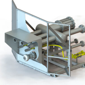
Flare unit for burning oil and gas condensate
A horizontal flare installation with manual remote ignition and flame control is designed for periodic and continuous disposal by burning oil, oil emulsion with a water cut of up to 25% and gas condensate.
Technical characteristics
- Consumption of burned liquid: 1-32 m³ per hour
- Pressure of the burned liquid: 1.0 MPa
- Supply air pressure: 1.0 MPa
- Combustion air flow: up to 18 nm³ per minute
- Fuel gas consumption: 2-4 nm³ per hour
- Fuel gas pressure: 0.05-0.3 MPa
- Ambient air temperature: from -60°С to +50°С
Horizontal flare unit for recycling industrial waste
A horizontal flare installation with manual remote ignition and flame control is intended for periodic and continuous disposal by burning gas and industrial wastewater.
Technical characteristics
- Industrial wastewater consumption: 1-20 m³ per hour
- Gas consumption for combustion: 500-12000 nm³ per hour
- Gas consumption for pilot burner: 7-8 nm³ per hour
- Industrial wastewater pressure: 2.5 MPa
- Calculated gas pressure for combustion: 1.6 MPa
- Calculated gas pressure on the pilot burner: 1.6 MPa
- Ambient air temperature: from -60°С to +50°С
Horizontal flare unit for gas combustion
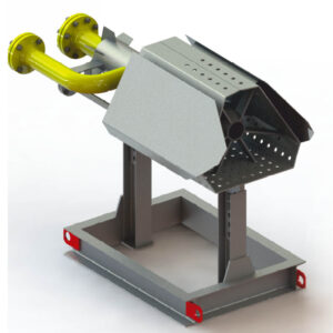
A horizontal flare installation for burning gas with manual remote ignition and control of the presence of flame is intended for periodic and continuous disposal by burning gas.
Technical characteristics
- Gas consumption for combustion of high-pressure HFCs: 500-3000 nm³ per hour
- Gas consumption for combustion of low-pressure HFCs: 33-180 nm³ per hour
- High pressure HFC gas operating pressure: 0.005-0.1 MPa
- Low pressure HFC gas operating pressure: 0.005-0.05 MPa
- High pressure HFC gas design pressure: 1.6 MPa
- Low pressure HFC gas design pressure: 1.6 MPa
- Ambient air temperature: from -60°С to +50°С
Vertical flare unit for gas combustion
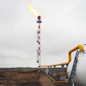
A vertical flare unit with automatic and manual remote ignition and flame presence control is designed for disposal by burning flammable hydrocarbon gases and vapors during periodic, constant and emergency discharges.
Technical characteristics
- Maximum consumption of flared gas: up to 1 million nm³ per day
- Minimum combustion gas consumption: not less than 10 nm³ per hour
- Combust gas pressure: 0.005-6.3 MPa
- Waste gas temperature: up to +300°C
- Density of discharged gas: 0.5-3.6 kg/m³
- Power consumption: no more than 2000 W
- Ambient air temperature: from -60°С to -50°С


